A
Traditional tools rely on GUID
Most IFC comparison tools use internal IFC GUIDs to determine whether two members are identical, making them suitable mainly for version comparison.
Even with completely different GUIDs, automatically find matching structural members across different software and compare differences.
Designed for architects and structural engineers to compare IFC models exported from Archicad, Revit, ETABS, SAP2000 and other software. During Public Beta, software compatibility and test cases will continue expanding.
Most IFC tools compare versions.
IFC Compare solves cross-software coordination.
Most IFC comparison tools use internal IFC GUIDs to determine whether two members are identical, making them suitable mainly for version comparison.
Even when two models are exported from different software and GUIDs are completely different, the system automatically finds corresponding members.
Supports one-to-one, one-to-many and many-to-one matching caused by different modeling approaches.
Designed for model consistency checking between Archicad, Revit, ETABS, SAP2000 and other software.
Built around structural members, the tool turns geometry and section differences into visual comparison results.
Designed for architecture and structural teams checking beam and column differences between BIM and structural analysis software.
IFC2x3 or later is recommended, including IFC2x3, IFC4, and IFC4x3. During the public beta, support will continue to expand based on how different software exports IFC data and geometry.
A simple and traceable process from model upload to report export.
Start with the short video to understand the basic workflow, then watch the full tutorial for detailed operation steps.
Things you may want to know before using the tool for the first time.
This tool compares differences between two structural IFC models.
You can upload two IFC models exported from different software, such as an Archicad IFC from the architect and a Revit, ETABS, or SAP2000 IFC from the structural engineer. The system helps identify section, position, angle, shape, and length differences in beams, columns, and other structural members.
In short, it helps you find inconsistencies between two models before drawing production, model coordination, or model exchange.
Most IFC comparison tools are mainly used to compare different versions of the same model, such as checking which members were added, deleted, or modified.
These tools usually rely on internal IFC GUIDs to determine whether two members are the same object, which makes them more suitable for version comparison within models generated by the same software.
However, in real BIM coordination, IFC models exported from different software such as Archicad, Revit, ETABS, and SAP2000 often have:
IFC Compare does not rely on GUIDs. Instead, it first analyzes each member’s axis, geometry, spatial position, length, and section information to determine which members actually represent the same structural member, then compares their differences.
In other words, this tool is designed to solve cross-software model coordination, not just simple model version comparison.
This tool is useful when architectural and structural models need to be checked against each other.
For structural engineers, it can be used before drawing production to compare IFC files exported from Revit and ETABS / SAP2000, helping confirm whether beam and column sizes and locations are consistent.
For architects, it can compare a structural IFC exported from Revit, ETABS, or SAP2000 with an architectural IFC, helping quickly identify size or position differences between the architectural and structural models.
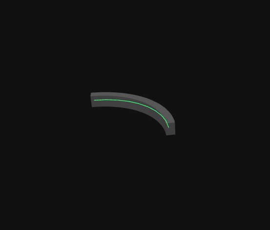
The system mainly reads two core pieces of information for each member: section and axis.
The section represents member size, such as RECT-500x800, BOX-300x300x12, or H-400x200x8x13.
The axis can be understood as the centerline along the member length. After extracting the axis, the system uses it to evaluate position, angle, shape, and length, then combines that with section size to determine whether the two members are consistent.
During pairing, the system uses each member in Model A as a reference and searches nearby for possible corresponding members in Model B.
If the two model coordinate systems are not aligned, corresponding beams or columns may be too far apart, causing the system to miss the correct pairing.
Therefore, when the two model origins or coordinates differ significantly, it is recommended to align the models first. The system can then search for corresponding members within a reasonable range and proceed with comparison.
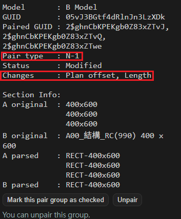
“Pairing” determines which member or members in Model B correspond to a member in Model A. Common pairing situations include:
“Comparison” checks whether paired members have differences, such as position, angle, section, shape, or length differences.
Simply put, pairing finds “which members belong together,” while comparison checks “whether there are differences within the pair.”
Ideally, the system can directly read each member’s section size from the IFC data.
In real projects, some members may be affected by joins, cuts, end trimming, conversion, or software-specific IFC export methods, making it difficult to infer the original section from geometry alone.
For example, a rectangular beam may be cut by columns, walls, or other elements at its ends, so its geometric shape is no longer a clean rectangle. In this case, geometry alone may not be enough to identify the correct section.
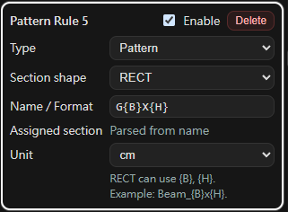
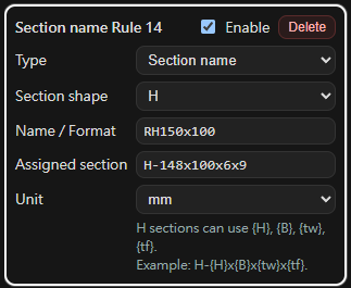
Section naming rules are used when geometry-based section detection is insufficient. The member name can then be used to specify the section size.
For example:
Automatic section naming detection: the system first attempts to find patterns in existing member names and apply possible section naming rules. Users can confirm, edit, or add rules to match project or company naming conventions.
If the automatic result is not as expected, you can correct it based on the type of issue.
These features help the tool adapt to different company modeling habits, IFC export results from different software, and project-specific checking requirements.
Yes.
Users can adjust comparison items and certain tolerances based on project needs. For example, you can choose whether to compare position, angle, shape, section, or length, and adjust thresholds for position offset, angle difference, and length difference.
This is useful for different stages of model checking. In early coordination, you may only want to confirm the main beam and column sizes. Before drawing production, you may want stricter checks for position, angle, and length differences.
The system temporarily processes uploaded IFC files and comparison results in order to complete the model comparison workflow.
The system regularly clears uploaded data and generated results. Temporary data is generally removed within 24 hours.
If you choose to provide IFC files through the feedback form and describe the issue you encountered, it will greatly help improve section parsing, pairing accuracy, and compatibility with IFC exports from different software.
This tool is an auxiliary IFC model difference checking tool. Results are intended for design review and coordination reference only and should still be finally confirmed by qualified professionals.
The tool currently focuses on comparing common structural member types such as beams and columns in IFC2x3 or later. IFC exports may differ between software, and certain special geometry representations, Brep, Boolean clipping, or non-standard export contents may not be fully parsed.
Large models may require longer processing time. For best results, upload simplified IFC models that include only the beams and columns you want to compare.
If you encounter any issues, have feedback, or are willing to share IFC test cases to help improve the tool, please contact: ifc.compare@gmail.com